 0755-23179541
  sales@oyii.net
Module OYI-1L311xF
1250Mb/s SFP 1310nm 10km Optical Transceiver
Module OYI-1L311xF
Product Description
OYI-1L311xF Small Form Factor Pluggable (SFP) transceivers are compatible with the Small Form Factor Pluggable Multi-Sourcing Agreement (MSA), The transceiver consists of five sections: the LD driver, the limiting amplifier, the digital diagnostic monitor, the FP laser and the PIN photo-detector, the module data link up to 10km in 9/125um single mode fiber.
The optical output can be disabled by a TTL logic high-level input of Tx Disable, and the system also 02 can disable the module via I2C. Tx Fault is provided to indicate that degradation of the laser. Loss of signal (LOS) output is provided to indicate the loss of an input optical signal of receiver or the link status with partner. The system can also get the LOS (or Link)/Disable/Fault information via I2C register access.
Product Features
1. Up to 1250Mb/s data links.
2. 1310nm FP laser transmitter and PIN photo-detector.
3. Up to 10km on 9/125µm SMF.
4. Hot-pluggable SFP footprint.
5. Duplex LC/UPC type pluggable optical interface.
6. Low power dissipation.
7. Metal enclosure, for lower EMI.
8. RoHS compliant and lead-free.
9. Support Digital Diagnostic Monitoring interface.
10. Single +3.3V power supply.
11. Compliant with SFF-8472.
12. Case operating temperature
Commercial: 0 ~ +70℃
Extended: -10 ~ +80℃
Industrial: -40 ~ +85℃
Applications
1. Switch to Switch Interface.
2. Gigabit Ethernet.
3. Switched Backplane Applications.
4. Router/Server Interface.
5. Other Optical Links.
Absolute Maximum Ratings
It has to be noted that the operation in excess of any individual absolute maximum ratings might cause permanent damage to this module.
|
Parameter |
Symbol |
Min |
Max |
Unit |
Notes |
|
Storage Temperature |
TS |
-40 |
85 |
°C |
|
|
Power Supply Voltage |
VCC |
-0.3 |
3.6 |
V |
|
|
Relative Humidity (non-condensation) |
RH |
5 |
95 |
% |
|
|
Damage Threshold |
THd |
5 |
|
dBm |
|
2.Recommended Operating Conditions and Power Supply Requirements
|
Parameter |
Symbol |
Min |
Typical |
Max |
Unit |
Notes |
|
Operating Case Temperature |
TOP |
0 |
|
70 |
°C |
commercial |
|
-10 |
|
80 |
extended |
|||
|
-40 |
|
85 |
industrial |
|||
|
Power Supply Voltage |
VCC |
3.135 |
3.3 |
3.465 |
V |
|
|
Data Rate |
|
|
1250 |
|
Mb/s |
|
|
Control Input Voltage High |
|
2 |
|
Vcc |
V |
|
|
Control Input Voltage Low |
|
0 |
|
0.8 |
V |
|
|
Link Distance (SMF) |
D |
|
|
10 |
km |
9/125um |
3.Pin Assignment and Pin Description
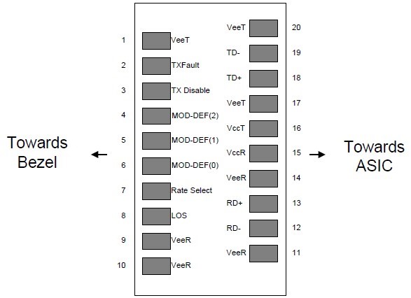
Figure1. Diagram of host board connector block pin numbers and names
|
PIN |
Name |
Name/Description |
Notes |
|
1 |
VEET |
Transmitter Ground (Common with Receiver Ground) |
1 |
|
2 |
TXFAULT |
Transmitter Fault. |
|
|
3 |
TXDIS |
Transmitter Disable. Laser output disabled on high or open. |
2 |
|
4 |
MOD_DEF(2) |
Module Definition 2. Data line for Serial ID. |
3 |
|
5 |
MOD_DEF(1) |
Module Definition 1. Clock line for Serial ID. |
3 |
|
6 |
MOD_DEF(0) |
Module Definition 0. Grounded within the module. |
3 |
|
7 |
Rate Select |
No connection required |
4 |
|
8 |
LOS |
Loss of Signal indication. Logic 0 indicates normal operation. |
5 |
|
9 |
VEER |
Receiver Ground (Common with Transmitter Ground) |
1 |
|
10 |
VEER |
Receiver Ground (Common with Transmitter Ground) |
1 |
|
11 |
VEER |
Receiver Ground (Common with Transmitter Ground) |
1 |
|
12 |
RD- |
Receiver Inverted DATA out. AC Coupled |
|
|
13 |
RD+ |
Receiver Non-inverted DATA out. AC Coupled |
|
|
14 |
VEER |
Receiver Ground (Common with Transmitter Ground) |
1 |
|
15 |
VCCR |
Receiver Power Supply |
|
|
16 |
VCCT |
Transmitter Power Supply |
|
|
17 |
VEET |
Transmitter Ground (Common with Receiver Ground) |
1 |
|
18 |
TD+ |
Transmitter Non-Inverted DATA in. AC Coupled. |
|
|
19 |
TD- |
Transmitter Inverted DATA in. AC Coupled. |
|
|
20 |
VEET |
Transmitter Ground (Common with Receiver Ground) |
1 |
Notes:
1. Circuit ground is internally isolated from chassis ground.
2. Laser output disabled on TDIS >2.0V or open, enabled on TDIS <0.8V.
3. Should be pulled up with 4.7k-10k ohms on host board to a voltage between 2.0V and 3.6V.MOD_DEF
(0) pulls line low to indicate module is plugged in.
4. This is an optional input used to control the receiver bandwidth for compatibility with multiple data rates (most likely Fiber Channel 1x and 2x Rates).If implemented, the input will be internally pulled down with > 30kΩ resistor. The input states are:
1) Low (0 – 0.8V): Reduced Bandwidth 2) (>0.8, < 2.0V): Undefined
3) High (2.0 – 3.465V): Full Bandwidth
4) Open: Reduced Bandwidth
5. LOS is open collector output should be pulled up with 4.7k-10k ohms on host board to a voltage between 2.0V and 3.6V. Logic 0 indicates normal operation; logic 1 indicates loss of signal.
Specification of Transmitter Electrical Characteristics
The following electrical characteristics are defined over the Recommended Operating Environment unless otherwise specified.
|
Parameter |
Symbol |
Min. |
|
Typical |
|
Max |
Unit |
Notes |
||
|
Power Consumption |
P |
|
|
|
|
0.85 |
W |
commercial |
||
|
|
|
|
|
0.9 |
Industrial |
|||||
|
Supply Current |
Icc |
|
|
|
|
250 |
mA |
commercial |
||
|
|
|
|
|
270 |
Industrial |
|||||
|
|
|
Transmitter |
|
|
|
|
||||
|
Single-ended Input Voltage Tolerance |
VCC |
-0.3 |
|
|
4.0 |
V |
|
|||
|
Differential Input Voltage Swing |
Vin,pp |
200 |
|
|
2400 |
mVpp |
|
|||
|
Differential Input Impedance |
Zin |
90 |
|
100 |
110 |
Ohm |
|
|||
|
Transmit Disable Assert Time |
|
|
|
|
5 |
us |
|
|||
|
Transmit Disable Voltage |
Vdis |
Vcc-1.3 |
|
|
Vcc |
V |
|
|||
|
Transmit Enable Voltage |
Ven |
Vee-0.3 |
|
|
0.8 |
V |
|
|||
|
Receiver |
||||||||||
|
Differential Output Voltage Swing |
Vout,pp |
500 |
|
|
900 |
mVpp |
|
|||
|
Differential Output Impedance |
Zout |
90 |
|
100 |
110 |
Ohm |
|
|||
|
Data output rise/fall time |
Tr/Tf |
|
|
100 |
|
ps |
20% to 80% |
|||
|
LOS Assert Voltage |
VlosH |
Vcc-1.3 |
|
|
Vcc |
V |
|
|||
|
LOS De-assert Voltage |
VlosL |
Vee-0.3 |
|
|
0.8 |
V |
|
|||
Optical Characteristics
The following optical characteristics are defined over the Recommended Operating Environment unless otherwise specified.
|
Parameter |
Symbol |
Min. |
Typical |
Max |
Unit |
Notes |
|
|
Transmitter |
|
||||
|
Center Wavelength |
λC |
1270 |
1310 |
1360 |
nm |
|
|
Spectrum Bandwidth(RMS) |
σ |
|
|
3.5 |
nm |
|
|
Average Optical Power |
PAVG |
-9 |
|
-3 |
dBm |
1 |
|
Optical Extinction Ratio |
ER |
9 |
|
|
dB |
|
|
Transmitter OFF Output Power |
POff |
|
|
-45 |
dBm |
|
|
Transmitter Eye Mask |
|
Compliant with 802.3z(class 1 laser safety) |
2 |
|||
|
|
Receiver |
|
||||
|
Center Wavelength |
λC |
1270 |
|
1610 |
nm |
|
|
Receiver Sensitivity (Average Power) |
Sen. |
|
|
-20 |
dBm |
3 |
|
Input Saturation Power (overload) |
Psat |
-3 |
|
|
dBm |
|
|
LOS Assert |
LOSA |
-36 |
|
|
dB |
4 |
|
LOS De-assert |
LOSD |
|
|
-21 |
dBm |
4 |
|
LOS Hysteresis |
LOSH |
0.5 |
|
|
dBm |
|
Notes:
1.Measure at 2^7-1 NRZ PRBS pattern
2.Transmitter eye mask definition.
3.Measured with Light source 1310nm, ER=9dB; BER =<10^-12
@PRBS=2^7-1 NRZ
4.When LOS de-asserted, the RX data+/- output is High-level(fixed).

Digital Diagnostic Functions
The following digital diagnostic characteristics are defined over the Recommended Operating Environment unless otherwise specified. It is compliant to SFF-8472 Rev10.2 with internal calibration mode. For external calibration mode please contact our sales staff.
|
Parameter |
Symbol |
Min. |
Max |
Unit |
Notes |
|
Temperature monitor absolute error |
DMI_ Temp |
-3 |
3 |
°C |
Over operating temp |
|
Supply voltage monitor absolute error |
DMI _VCC |
-0.15 |
0.15 |
V |
Full operating range |
|
RX power monitor absolute error |
DMI_RX |
-3 |
3 |
dB |
|
|
Bias current monitor |
DMI_ bias |
-10% |
10% |
mA |
|
|
TX power monitor absolute error |
DMI_TX |
-3 |
3 |
dB |
|
Mechanical Dimensions
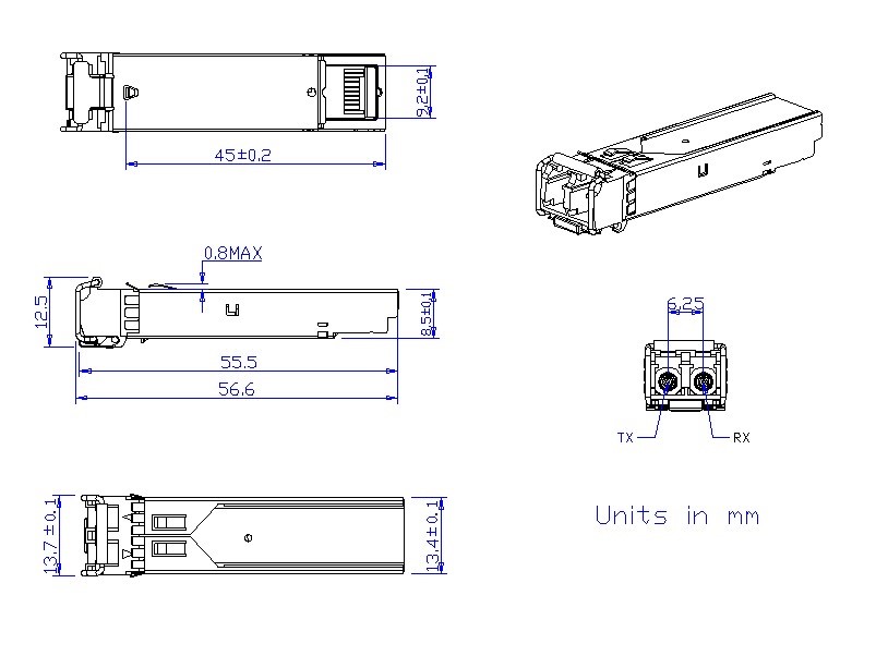
Figure2. Mechanical Outline
Ordering Information
|
Part Number |
Data Rate (Gb/s) |
Wavelength (nm) |
Transmission Distance(km) |
Temperature (oC) (Operating Case) |
|
OYI-1L311CF |
1.25 |
1310 |
10km SMF |
0~70 commercial |
|
OYI-1L311EF |
1.25 |
1310 |
10km SMF |
-10~80 Extended |
|
OYI-1L311IF |
1.25 |
1310 |
10km SMF |
-40~85 Industrial |
-
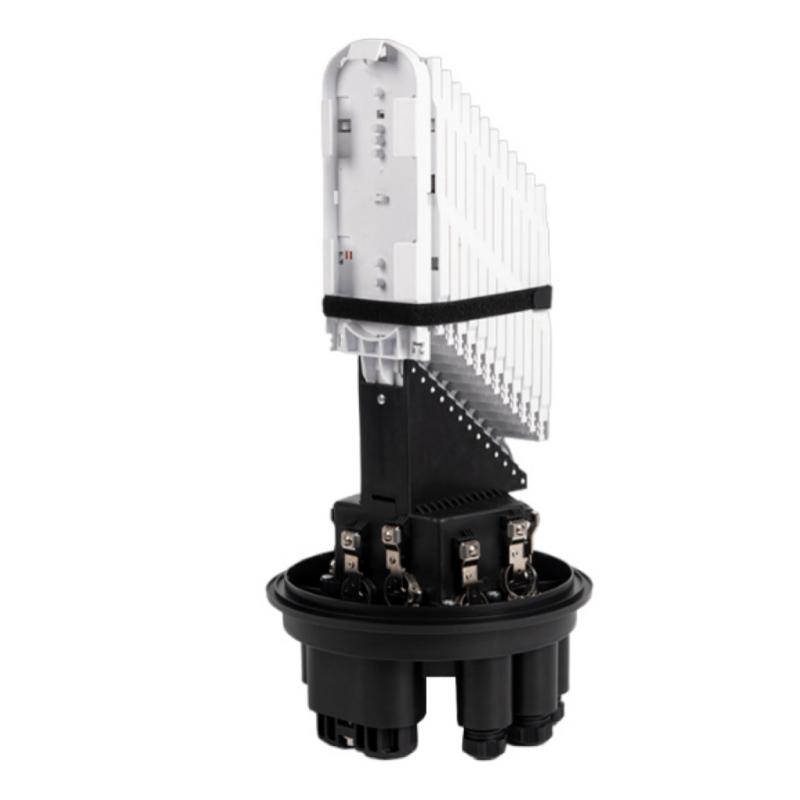
OYI-FOSC-D109M
The OYI-FOSC-D109M dome fiber optic splice closure is used in aerial, wall-mounting, and underground applications for the straight-through and branching splice of the fiber cable. Dome splicing closures are excellent protection of fiber optic joints from outdoor environments such as UV, water, and weather, with leak-proof sealing and IP68 protection.
The closure has 10 entrance ports on the end (8 round ports and 2 oval port). The shell of the product is made from ABS/PC+ABS material. The shell and the base are sealed by pressing the silicone rubber with the allocated clamp. The entry ports are sealed by heat-shrinkable tubes. The closures can be opened again after being sealed and reused without changing the sealing material.
The closure’s main construction includes the box, splicing, and it can be configured with adapters and optical splitters.
-

OYI-ODF-SNR-Series Type
The OYI-ODF-SNR-Series type optical fiber cable terminal panel is used for cable terminal connection and can also be used as a distribution box. It has a 19″ standard structure and is slidable type fiber optic patch panel. It allows for flexible pulling and is convenient to operate. It is suitable for SC, LC, ST, FC, E2000 adapters, and more.
The rack mounted optical cable terminal box is a device that terminates between the optical cables and the optical communication equipment. It has the functions of splicing, termination, storing, and patching of optical cables. The SNR-series sliding and without rail enclosure allows for easy access to fiber management and splicing. It is a versatile solution available in multiple sizes (1U/2U/3U/4U) and styles for building backbones, data centers, and enterprise applications.
-

10&100&1000M Media Converter
10/100/1000M adaptive fast Ethernet optical Media Converter is a new product used for optical transmission via high-speed Ethernet. It is capable of switching between twisted pair and optical and relaying across 10/100 Base-TX/1000 Base-FX and 1000 Base-FX network segments, meeting long-distance, high – speed and high-broadband fast Ethernet workgroup users’ needs, achieving high-speed remote interconnection for up to 100 km’s relay-free computer data network. With steady and reliable performance, design in accordance with Ethernet standard and lightning protection, it is particularly applicable to a wide range of fields requiring a variety of broadband data network and high-reliability data transmission or dedicated IP data transfer network, such as telecommunication, cable television, railway, military, finance and securities, customs, civil aviation, shipping, power, water conservancy and oilfield etc, and is an ideal type of facility to build broadband campus network, cable TV and intelligent broadband FTTB/FTTH networks.
-

24-48Port, 1RUI2RUCable Management Bar Included
1U 24 Ports(2u 48) Cat6 UTP Punch Down Patch Panel for 10/100/1000Base-T and 10GBase-T Ethernet. The 24-48 port Cat6 patch panel shall terminate 4-pair, 22-26 AWG, 100 ohm unshielded twisted pair cable with 110 punch down termination, which is color-coded for T568A/B wiring, providing the perfect 1G/10G-T speed solution for PoE/PoE+ applications and any voice or LAN application.
For hassle-free connections, this Ethernet patch panel offers straight Cat6 ports with 110-type termination, making it easy to insert and remove your cables. The clear numbering on the front and back of the network patch panel enables quick and easy identification of cable runs for efficient system management. Included cable ties and a removable cable management bar help organize your connections, cut down on cord clutter, and maintain stable performance.
-

GJFJKH
Jacketed aluminum interlocking armor provides the optimal balance of ruggedness, flexibility and low weight. The Multi-Strand Indoor Armored Tight-Buffered 10 Gig Plenum M OM3 Fiber Optic Cable from Discount Low Voltage is a good choice inside buildings where toughness is required or where rodents are a problem. These also are ideal for manufacturing plants and harsh industrial environments as well as high-density routings in data centers. Interlocking armor can be used with other types of cable, including indoor/outdoor tight-buffered cables.
-
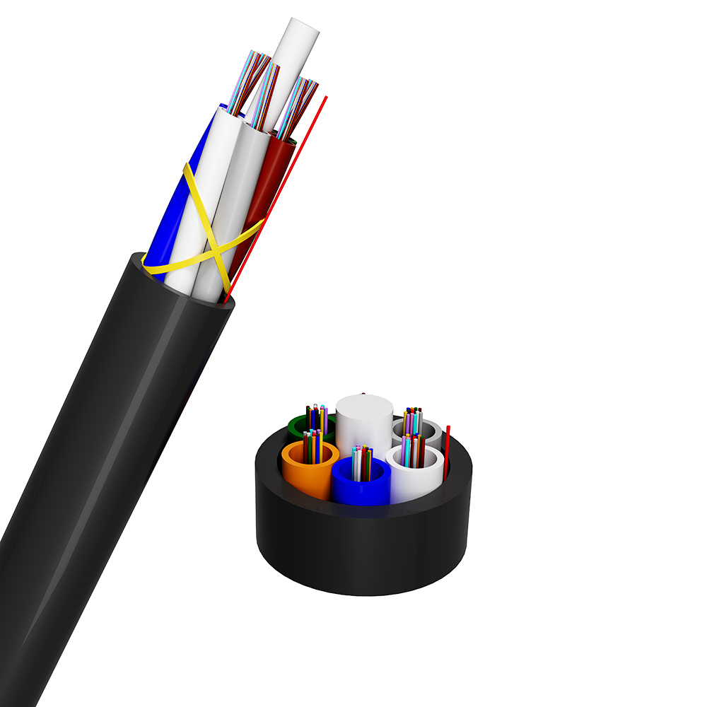
Air Blowing Mini Optical Fibre Cable
The optical fiber is placed inside a loose tube made of high-modulus hydrolyzable material. The tube is then filled with thixotropic, water-repellent fiber paste to form a loose tube of optical fiber. A plurality of fiber optic loose tubes, arranged according to color order requirements and possibly including filler parts, are formed around the central non-metallic reinforcement core to create the cable core via SZ stranding. The gap in the cable core is filled with dry, water-retaining material to block water. A layer of polyethylene (PE) sheath is then extruded.
The optical cable is laid by air blowing microtube. First, the air blowing microtube is laid in the outer protection tube, and then the micro cable is laid in the intake air blowing microtube by air blowing. This laying method has a high fiber density, which greatly improves the utilization rate of the pipeline. It is also easy to expand the pipeline capacity and diverge the optical cable.
If you're looking for a reliable, high-speed fibre optic cable solution, look no further than OYI. Contact us now to see how we can help you stay connected and take your business to the next level.
