 0755-23179541
  sales@oyii.net
.png) 8618926041961
8618926041961
1.25Gbps 1550nm 60Km LC DDM
SFP Transceiver
1.25Gbps 1550nm 60Km LC DDM
Product Features
1. SFP package with LC connector.
2. 1550nm DFB laser and PIN photo detector.
3. Up to 60Km transmission on SMF.
4. +3.3V single power supply.
5. LVPECL compatible data input/output interface.
6. Low EMI and excellent ESD protection.
7. laser safety standard IEC-60825 compliant.
8. Compatible with RoHS.
9. Digital Diagnostic SFF-8472 compliant.
10. Signal Ground Isolated to Case.
Application
1. 1.25Gb/s 1000Base-LX Ethernet.
2. Dual Rate 1.06 / 2.125 Gb/s Fiber Channel.
Absolute Maximum Ratings:
|
Parameter |
Symbol |
Minimum |
Maximum |
Units |
|
Storage Temperature |
Tst |
-40 |
+85 |
℃ |
|
Supply Voltage |
Vcc |
0 |
+3.6 |
V |
|
Operating Relative Humidity |
RH |
5 |
95 |
% |
Operation Environment:
|
Parameter |
Symbol |
Min |
Typical |
Max |
Units |
|
Supply Voltage |
Vcc |
3.15 |
3.3 |
3.45 |
V |
|
Operating Case Temperature |
Tc |
0 |
|
+70 |
|
|
Power Dissipation |
|
|
|
1 |
W |
|
Data Rate |
|
|
1.25 |
|
Gbps |
Optical Characteristics
(Ambient Operating Temperature 0℃ to +70℃, Vcc =3.3 V)
|
Parameter |
Symbol |
Min. |
Typ. |
Max. |
Units |
|
Transmitter Section |
|||||
|
Center Wavelength |
λo |
1540 |
1550 |
1560 |
nm |
|
Spectral Width (RMS) |
△λ |
- |
- |
1 |
nm |
|
Average Output Power |
Po |
-5 |
- |
0 |
dBm |
|
Extinction Ratio |
Er |
8 |
- |
|
dB |
|
Rise/Fall Time (20%~80%) |
Tr/Tf |
|
|
180 |
ps |
|
Total jitter |
Tj |
|
|
0.43 |
UI |
|
Optical Eye Diagram |
IEEE 802.3z and ANSI Fiber Channel Compatible |
||||
|
Receiver Section |
|||||
|
Center Wavelength |
λo |
1260 |
|
1620 |
nm |
|
Receiver Sensitivity |
Rsen |
|
|
-24 |
dBm |
|
Receiver Overload |
Rov |
-3 |
|
|
dBm |
|
Return Loss |
|
12 |
|
|
dB |
|
LOS Assert |
LOSA |
-36 |
|
|
dBm |
|
LOS Dessert |
LOSD |
|
|
-25 |
dBm |
|
LOS Hysteresis |
|
0.5 |
|
5 |
|
Electrical Characteristics
(Ambient Operating Temperature 0℃ to +70℃, Vcc =3.3 V)
|
Parameter |
Symbol |
Min. |
Typ. |
Max. |
unit |
|
|
Transmitter Section |
||||||
|
Input Differential Impendence |
Zin |
90 |
100 |
110 |
Ohm |
|
|
Data Input Swing Differential |
Vin |
500 |
|
2400 |
mV |
|
|
TX Disable |
Disable |
|
2.0 |
|
Vcc |
V |
|
Enable |
|
0 |
|
0.8 |
V |
|
|
TX Fault |
Assert |
|
2.0 |
|
Vcc |
V |
|
Deassert |
|
0 |
|
0.8 |
V |
|
|
Receiver Section |
||||||
|
Output differential impendence |
Zout |
|
100 |
|
Ohm |
|
|
Data Input Swing Differential |
Vout |
370 |
|
2000 |
mV |
|
|
Rx_LOS |
Assert |
|
2.0 |
|
Vcc |
V |
|
Deassert |
|
0 |
|
0.8 |
V |
|
EEPROM INFORMATION(A0)
|
Addr |
Field Size (Bytes) |
Name of Field |
HEX |
Description |
|
0 |
1 |
Identifier |
03 |
SFP |
|
1 |
1 |
Ext. Identifier |
04 |
MOD4 |
|
2 |
1 |
Connector |
07 |
LC |
|
3-10 |
8 |
Transceiver |
00 00 00 02 12 00 0D 01 |
Transmitter Code |
|
11 |
1 |
Encoding |
01 |
8B10B |
|
12 |
1 |
BR, nominal |
0D |
1250M bps |
|
13 |
1 |
Reserved |
00 |
|
|
14 |
1 |
Length (9um)-km |
3C |
60km |
|
15 |
1 |
Length (9um) |
64/C8/FF |
|
|
16 |
1 |
Length (50um) |
00 |
|
|
17 |
1 |
Length (62.5um) |
00 |
|
|
18 |
1 |
Length (copper) |
00 |
|
|
19 |
1 |
Reserved |
00 |
|
|
20-35 |
16 |
Vendor name |
57 49 4E 54 4F 50 20 20 20 20 20 20 20 20 20 20 |
WINTOP |
|
36 |
1 |
Reserved |
00 |
|
|
37-39 |
3 |
Vendor OUI |
00 00 00 |
|
|
40-55 |
16 |
Vendor PN |
xx xx xx xx xx xx xx xx xx xx xx xx xx xx xx xx |
ASC II |
|
56-59 |
4 |
Vendor rev |
31 2E 30 20 |
V1.0 |
|
60-61 |
2 |
Wavelength |
06 0E |
1550nm |
|
62 |
1 |
Reserved |
00 |
|
|
63 |
1 |
CC BASE |
XX |
Check sum of byte 0~62 |
|
64-65 |
2 |
Options |
00 1A |
LOS, TX_DISABLE, TX_FAULT |
|
66 |
1 |
BR, max |
32 |
50% |
|
67 |
1 |
BR, min |
32 |
50% |
|
68-83 |
16 |
Vendor SN |
00 00 00 00 00 00 00 00 00 00 00 00 00 00 00 00 |
Unspecified |
|
84-91 |
8 |
Vendor date code |
XX XX XX 20 |
Year, Month, Day |
|
92-94 |
3 |
Reserved |
00 |
|
|
95 |
1 |
CC_EXT |
XX |
Check sum of byte 64~94 |
|
96-255 |
160 |
Vendor specific |
|
Diagnostics
|
Parameter |
Range |
Accuracy |
Unit |
Calibration |
|
Temperature |
0~70 |
±3 |
℃ |
Internal |
|
Voltage |
3.15~3.45 |
0.1 |
V |
Internal |
|
Bias Current |
10~80 |
±2 |
mA |
Internal |
|
Tx Power |
-6~1 |
±2 |
dBm |
Internal |
|
Rx Power |
-26~-3 |
±3 |
dBm |
Internal |
Pin Description
|
Pins |
Name |
Description |
NOTE |
|
1 |
VeeT |
Transmitter Ground |
|
|
2 |
Tx Fault |
Transmitter Fault Indication |
1 |
|
3 |
Tx Disable |
Transmitter Disable |
2 |
|
4 |
MOD DEF2 |
Module Definition 2 |
3 |
|
5 |
MOD DEF1 |
Module Definition 1 |
3 |
|
6 |
MOD DEF0 |
Module Definition 0 |
3 |
|
7 |
Rate Select |
Not Connected |
|
|
8 |
LOS |
Loss of Signal |
4 |
|
9 |
VeeR |
Receiver Ground |
|
|
10 |
VeeR |
Receiver Ground |
|
|
11 |
VeeR |
Receiver Ground |
|
|
12 |
RD- |
Inv. Received Data Output |
S |
|
13 |
RD+ |
IReceived Data Output |
S |
|
14 |
VeeR |
Receiver Ground |
|
|
15 |
VccR |
Receiver Power |
|
|
16 |
VccT |
Transmitter Power |
|
|
17 |
VeeT |
Transmitter Ground |
|
|
18 |
TD+ |
Transmit Data Input |
6 |
|
19 |
TD- |
Inv. Transmit Data Input |
6 |
|
20 |
VeeT |
Transmitter Ground |
Notes:
1. TX Fault is an open collector output, which should be pulled up with a 4.7k~10kΩ resistor on the host board to a voltage between 2.0V and Vcc+0.3V. Logic 0 indicates normal operation; logic 1 indicates a laser fault of some kind. In the low state, the output will be pulled to less than 0.8V.
2. TX Disable is an input that is used to shut down the transmitter optical output. It is pulled up with in the module with a 4.7k~10kΩ resistor. Its states are:
Low (0~0.8V): Transmitter on
(>0.8V, <2.0V): Undefined
High (2.0~3.3V): Transmitter Disabled
Open: Transmitter Disabled
3. MOD-DEF 0,1,2 are the module definition pins. They should be pulled up with a 4.7k~10kΩresistor on the host board. The pull-up voltage shall be VccT or VccR.
MOD-DEF 0 is grounded by the module to indicate that the module is present.
MOD-DEF 1 is the clock line of two wire serial interface for serial ID.
MOD-DEF 2 is the data line of two wire serial interface for serial ID.
4. LOS is an open collector output, which should be pulled up with a 4.7k~10kΩ resistor on the host board to a voltage between 2.0V and Vcc+0.3V. Logic 0 indicates normal operation; logic 1 indicates loss of signal. In the low state, the output will be pulled to less than 0.8V.
5. These are the differential receiver output. They are internally AC-coupled 100Ω differential lines which should be terminated with 100Ω (differential) at the user SERDES.
6. These are the differential transmitter inputs. They are AC-coupled, differential lines with 100Ω differential termination inside the module.
Recommended Application Circuit

Outline Dimensions (mm)

-
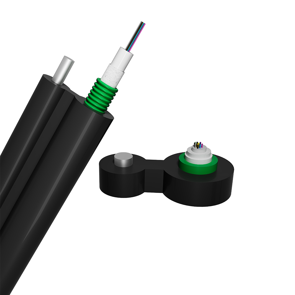
Central Loose Tube Stranded Figure 8 Self-suppo...
The fibers are positioned in a loose tube made of PBT. The tube is filled with a water-resistant filling compound. The tubes (and the fillers) are stranded around the strength member into a compact and circular core. Then, the core is wrapped with swelling tape longitudinally. After part of the cable, accompanied by the stranded wires as the supporting part, is completed, it is covered with a PE sheath to form a figure-8 structure. -
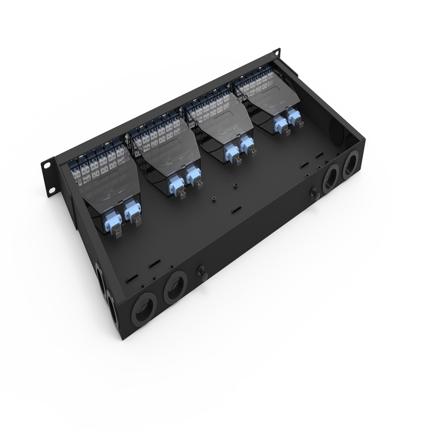
OYI-ODF-MPO-Series Type
The rack mount fiber optic MPO patch panel is used for cable terminal connection, protection, and management on trunk cable and fiber optic. It is popular in data centers, MDA, HAD, and EDA for cable connection and management. It is installed in a 19-inch rack and cabinet with an MPO module or MPO adapter panel. It has two types: fixed rack mounted type and drawer structure sliding rail type. It can also be widely used in optical fiber communication systems, cable television systems, LANs, WANs, and FTTX. It is made with cold rolled steel with Electrostatic spray, providing strong adhesive force, artistic design, and durability. -
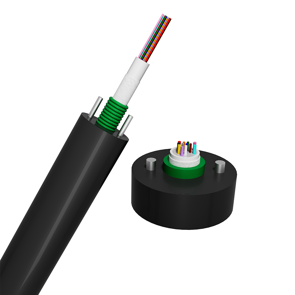
Central Loose Tube Armored Fiber Optic Cable
The two parallel steel wire strength members provide enough tensile strength. The uni-tube with special gel in the tube offers protection for the fibers. The small diameter and light weight make it easy to lay. The cable is anti-UV with a PE jacket, and is resistant to high and low temperature cycles, resulting in anti-aging and a longer lifespan. -
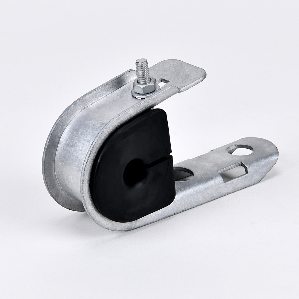
J Clamp J-Hook Big Type Suspension Clamp
OYI anchoring suspension clamp J hook is durable and of good quality, making it a worthwhile choice. It plays an important role in many industrial settings. The main material of the OYI anchoring suspension clamp is carbon steel, with an electro galvanized surface that prevents rust and ensures a long lifespan for pole accessories. The J hook suspension clamp can be used with the OYI series stainless steel bands and buckles to fix cables onto poles, playing different roles in different places. Different cable sizes are available. The OYI anchoring suspension clamp can also be used to link signs and cable installations on posts. It is electro galvanized and can be used outdoors for over 10 years without rusting. It has no sharp edges, with rounded corners, and all items are clean, rust free, smooth, and uniform throughout, free from burrs. It plays a huge role in industrial production. -
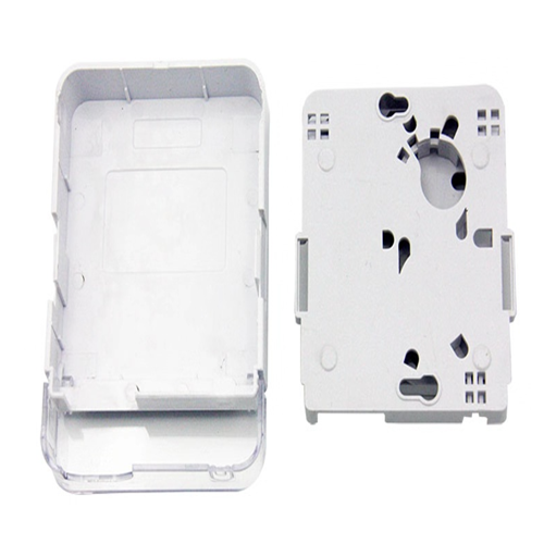
OYI-ATB02C Desktop Box
OYI-ATB02C one ports terminal box is developed and produced by the company itself. The product’s performance meets the requirements of industry standards YD/T2150-2010. It is suitable for installing multiple types of modules and can be applied to the work area wiring subsystem to achieve dual-core fiber access and port output. It provides fiber fixing, stripping, splicing, and protection devices, and allows for a small amount of redundant fiber inventory, making it suitable for FTTD (fiber to the desktop) system applications. The box is made of high-quality ABS plastic through injection molding, making it anti-collision, flame retardant, and highly impact-resistant. It has good sealing and anti-aging properties, protecting the cable exit and serving as a screen. It can be installed on the wall. -
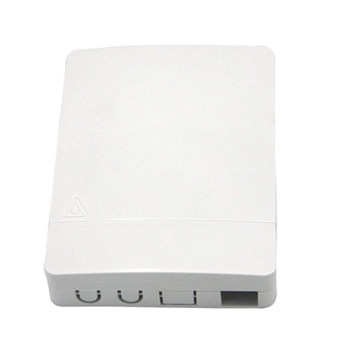
OYI-ATB02D Desktop Box
OYI-ATB02D double-port desktop box is developed and produced by the company itself. The product’s performance meets the requirements of industry standards YD/T2150-2010. It is suitable for installing multiple types of modules and can be applied to the work area wiring subsystem to achieve dual-core fiber access and port output. It provides fiber fixing, stripping, splicing, and protection devices, and allows for a small amount of redundant fiber inventory, making it suitable for FTTD (fiber to the desktop) system applications. The box is made of high-quality ABS plastic through injection molding, making it anti-collision, flame retardant, and highly impact-resistant. It has good sealing and anti-aging properties, protecting the cable exit and serving as a screen. It can be installed on the wall.
If you're looking for a reliable, high-speed fibre optic cable solution, look no further than OYI. Contact us now to see how we can help you stay connected and take your business to the next level.
